DIY Assembly of an Electric Bike Power System and Usage Report
Preface
The original vehicle used five 12V lead-acid batteries — a two-wheeler from a certain domestic traditional brand. After less than two years of use, its range had dropped to under 30 km.
Although I could have exchanged the old batteries for new lead-acid ones, lead-acid has a drawback: as the charge level falls, the output voltage also drops, and the vehicle’s power performance degrades significantly. So I decided to DIY a lithium-ion power system.
DIY Process
There weren’t many cell options: either ternary lithium (NMC/NCA) or lithium iron phosphate (LFP).
Compared side-by-side, ternary lithium clearly has higher energy density and overall better performance, but it can be temperamental. In normal use it’s usually fine, but if something goes wrong, it can be disastrous.
So I chose lithium iron phosphate as the final solution.
LFP has many advantages: stable discharge voltage and high safety, though its low-temperature performance isn’t great. However, I live in a city in the southeast corner of China — low temperatures aren’t a concern.
Because of manufacturing reasons, LFP cells have slightly worse consistency, so an active-balancing protection board should be used.
Both the cells and the protection board were sourced from Chinese brands; I won’t advertise the specific brand names here.
During the National Day (Golden Week) holiday I bought 20 cells and asked the seller to balance-test them.
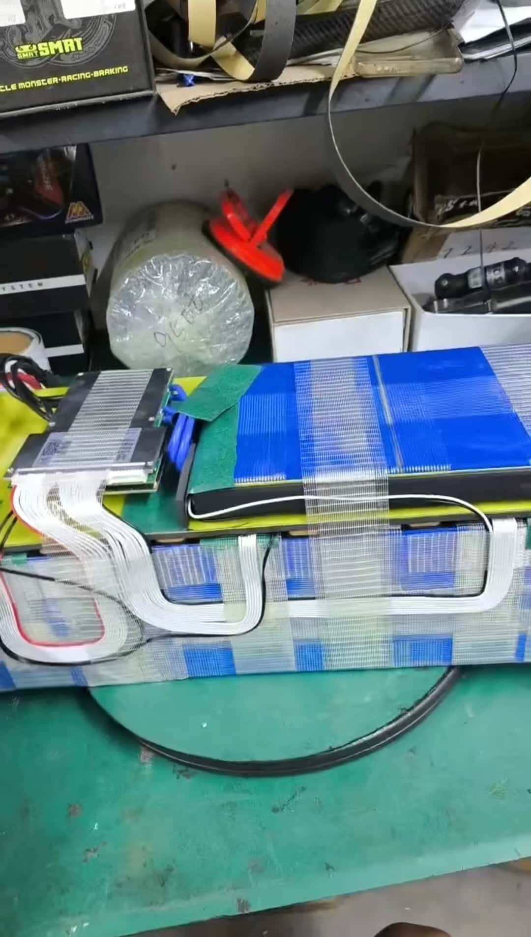
Next came grouping and welding the cells, testing, and packaging. The preliminary finished product looks like this:
I didn’t replace the motor or controller — I ran some basic tests. Top speed is 40 km/h with 40 A current. That’s plenty for city commuting. The controller looks like this:
The power battery pack was assembled in a custom stainless steel case with explosion-proof, shock-absorbing foam inside. The installed pack looks like this:
Finally, I tuned the protection board parameters for the power pack. The initial app interface is shown below.
Working with the Power Battery Protection Board
Protection Board Information
Battery Power
Shows the total instantaneous power output or input of the battery pack. The value is the product of the current pack voltage and the absolute value of the pack current. Unit: W.Average Cell Voltage
Shows the average voltage of the individual cells in the pack. Unit: V.Battery Capacity
Indicates the actual battery capacity calculated by the protection board’s high-precision SOC algorithm. Unit: AH. (This value updates only after the battery undergoes a full discharge and charge cycle.)Maximum Voltage Difference
The maximum voltage difference is the voltage gap between the highest and lowest cell in the pack. Unit: V.Balancing Current
When the balancing function is enabled and balancing conditions are met, this field displays the real-time balancing current. Unit: A.
During balancing, in the real-time cell voltage display, blue indicates a discharging cell and red indicates a charging cell. A negative balancing current means the cell is discharging (blue will flash), and a positive balancing current means the cell is charging (red will flash).
The protection board uses active balancing: it takes charge from higher-voltage cells, stores it in the board, then supplies it to lower-voltage cells.
Protection Board Parameter Tuning
The protection board has many parameters, and incorrect configuration can damage the battery. Do not adjust parameters unless you fully understand their meaning!
Below are the most important parameters and their functions.
Number of Cells
The number of cells indicates how many individual cells are in the pack. Set this value accurately before use; otherwise the protection board will not work properly.Balancing Trigger Voltage Difference
When balancing is enabled, balancing starts if the pack’s maximum voltage difference exceeds this value and an individual cell’s voltage is above the balancing start voltage. Balancing continues until the difference falls below this trigger or the cell voltage drops below the start voltage. For example, if the trigger is set to 0.01 V, balancing starts when the pack difference exceeds 0.01 V and stops when it falls below 0.01 V. (Recommendation: for batteries ≥ 50 AH set the trigger to 0.005 V; for batteries < 50 AH set it to 0.01 V.)Balancing Start Voltage
The balancing start voltage controls the voltage stage at which balancing is allowed. Balancing is only triggered when a cell’s voltage exceeds this value and the pack’s maximum voltage difference exceeds the balancing trigger.“Cell Overcharge Voltage” and “Cell Overcharge Recovery”
“Cell overcharge voltage” refers to the saturation voltage of a cell. If any cell’s voltage exceeds this value, a ‘cell overcharge alarm’ is triggered and the protection board disables the charging MOSFET, preventing further charging (discharging is still allowed). After the alarm, charging is only re-enabled when all cell voltages fall below the “cell overcharge recovery” value.“Cell Under-voltage Protection” and “Cell Under-voltage Recovery”
“Cell under-voltage protection” is the cutoff voltage for a cell. If any cell’s voltage falls below this value, a ‘cell under-voltage alarm’ is triggered and the protection board disables the discharging MOSFET, preventing further discharging (charging is still allowed). After the alarm, discharging is re-enabled only when all cell voltages rise above the “cell under-voltage recovery” value.Recommended Charging Voltage
“Recommended charging voltage” is the BMS-recommended charging range or value for optimal battery performance and safety. This recommendation is based on cell type, manufacturer guidance, BMS design characteristics, and charger features.“SOC-100% Voltage” and “SOC-0% Voltage”
“SOC-100% voltage” is the voltage when a cell’s SOC is considered 100%. This value is slightly lower than the cell overcharge voltage; when a cell’s voltage is greater than or equal to this value it’s considered full. “SOC-0% voltage” is the voltage when a cell’s SOC is considered 0%. This value is slightly higher than the cell under-voltage protection voltage; when a cell’s voltage is less than or equal to this value it’s considered empty.Auto Shutdown Voltage
The auto shutdown voltage is the minimum voltage at which the protection board remains operational. When the highest cell voltage in the pack drops below this value, the protection board shuts down. This value must be lower than the “cell under-voltage protection” setting.
My Configured Parameter Values
(Welcome to discuss — updates will be posted!)